Tag Archives: siamese port

Deeper into the virtual siamese rabbit hole, lots deeper

The odd thing is that the Siamese port head is in dire need of some investigations on a somewhat more fundamental level than they thought possible when they designed it many many moons ago. Ideally you would have a dyno mule rigged with a full set of  ultra fast in-cylinder and in manifold and above valve pressure transducers, multiple  lambda sensors , air mass sensors and EGT’s. If I win the lottery it would  think about it, but as I don’t play things look a tad bleak on that front.

Not long ago something like 1D simulations would have been the sole domain of OEM’s with very deep pockets and CFD was just used on fighter jets design and by NASA.  Things have changed quite a bit in the last few years. Eng Mod 4T costs about 400$ (and that would not even cover the cost of one week of licensing of the big boys) and CFD packages can be had for ..freee.

Trouble with free is that it was usually experimental code that involves a unix/linux prompt, a degree of two in advanced mathematics and a lot patience to get the thing running for your hardware. Older laptops do quite well in the getting it running on Linux department as they present a fairly constant configuration and as they are old, drivers and such actually exist. But old means slow and CFD needs fast. On the other hand your laptop probably has a lot more computational horses under the hood than they had when they designed the space shuttle so you really can’t complain . Just for your inner nerd : The Cray X-MP/22 that they used in 1986 for weather forecasts could manage 800 Mflops.. my vintage laptop manages 1.2 Gflops to about 3.5 Gflops . Having said that you will still want all the HP you can, if you want you compute larger simulations and not wait a week or so.But as it is 2014 you have working cloud computing , granting access to resources that would be unheard off 5 year ago for not all that much money.  Using EC2 ( amazon elastic cloud) you can have a reaaaly big computer as pay as you use it. It makes all kinds of sense. For 1000$ you can either buy a computer that will be outdated next week or have several thousand hours of computing time that you can initiate off your older laptop or desktop .

Something like CAE linux will provide you with a linux (Ubuntu) distribution ready installed with all the stuff you could want . I have negligible Linux experience (late nineties Power PC linux.. it was just too hard to make it do anything useful) but I managed to make it boot from a USB stick and install in on an old 80 GB external USB HD in about 30 minutes, and whats more, everything seems to work including WIFI and trackpads. I will still have to do a LOT of reading to make it do stuff and make sense as the packages include several very powerful (and thus complicated) CFD solvers , CAD , FEM  etc etc. Those are not programmed by hobbyists but often products of government funded, university and research programs like that of the EDF (French national electricity grid) involving very smart people writing millions of lines of code.

My nerd quotient has tripled as well, but now come the hard part.. making it do stuff.

The target will be a halfway realistically  Siamese model using boundary conditions provided by Eng mod 4T where you can visualise not only the cross talk between adjacent cylinder but also with the other pair. Don’t hold your breath though 🙂

btw

Here is the best super short introduction to CFD I have found so far.

The big scary differential equations are actually just your basic high school physics ones when look at it like this.

Tagged , , , , ,

10 minute porting.

After 15 minutes abs and the much improved 12 minutes abs.  I present 10 minute porting..

12g202 head

Just to show that the seat area is quite critical I simply put in a 5 minute three angle seat (little more than a freshen up) a valve with little more than 0.3mm backcut and a quick ”clean” using a small flap wheel ( and a big grinder) about 1 cm into the port. Takes little more than 10 minutes if even that.

It still looks pretty nasty and nothing like it would after proper porting.

DIRT-PORTING

Gains? .. not huge but significant ~3 CFM on 71 cfm total flow over the entire range of 3-12 mm lift  so about 5% on average gain.

Investment in time/effort: very little.

Next up is the chamber. But I will need a head gasket to see how far I can go.

Idea is to get some measure of pressure recovery and it will probably involve sinking the seat deeper in the head (yup..) and laying back the chamber but not cutting it all the way down to the bottom like Vizard suggests.

that i’ll be the 100 minute porting episode

Tagged , , , , , , , , , , ,

Instability problems in the simulation.

In my quest the get a decent Siamese model up and running I have hit a snag. At certain rpms (around 3000) the  model does not want to stabilize. I think that the torque dip I have at lower rpm’s is down to this behaviour. As these programs work using iteration cycles it needs a few for the model to reach an equilibrium.  Normally 8-10 cycles suffice, however the LCB I painstakingly modelled makes for a model that still is all over the place after 25 cycles with no signs of any stable pattern . Thing is, you have to stare at the number while they are being produced.. Dr N from Vannik is looking into it . Hopefully he has some answers.

meanwhile I feel like I’m in the matrix.

addendum:

The glitch in the matrix was…. tadaaah a bit of user error ( managed to reverse a port) and the cam is just odd and reverse flows quite badly. Dr Neels has provided (that is what I call customer service) some extra tricks to help with analysing siamese heads and I will have to see what I can learn there

Tagged , , , , , , , ,

More siamese simulation.. 1+4 vs 2+3.. place your bets

Image

In earlier instalments of this quest (if getting fully lost can be considered a quest) I virtually build a 1078cc small bore engine with an unported 202 head.

Now for a 12g940 head with flow numbers I measured on a ported head. A 1380cc with the usual parts : Big LCB, MS intake with  HIF 44, 1.5 rockers and a short exponential stack somewhat akin to what I have on the shelf from Calver ST.

First the bottom end.

takes about 1 minute to set up.. no problems there

Head.

Quite a bit trickier. I decided to use only half of the actual port lengths (then add it to the exhaust part) as it was slightly easier when modelling a 3-1 siamese ( which is exactly the same topography as an LCB btw, just with different lengths primairies). Valve sizes are 35.7/29mm nothing odd here. Max flow is 122 cfm @28 inch H20

Cam is a near as a could get it to a Crane VP3c based on what Vizard published. Short duration, high lift cam on a billet. 276/288  0.465/0.489 inch lift ( so quite aggressive). According to Vizard it is the best thing since sliced bread (he does tend to big it up a bit.. or three bits) and on page 302 of the big yellow book its makes 130 bhp at about 7300 rpm .

LCB:

modelling an LCB makes your head hurt the first few times. Just in case you have EngMod4t.

i’ll give a brief overview:

Its a 4-2-1 type 1+4 2+3 where the primaries of 2+3 are 35mm long (the rest is in the head if you don’t do that the section will be too short to model if you are out of luck). The end pipes are 35mm Plus 11 inch ( 1-3/8 inch diam) and connect to connector pipe (there is a logic to it) 5, the centre branch is a connector pipe  connecting 2+3 to Number 6 and 25 inch x 1.5 inch diameter.. the whole lot then goes into the collector that is 48 mm diameter and in my case 300mm long.

headache yet ?

Muffler ?…. Don’t need one, as my simulated neighbours are deaf, and it adds quite a bit to the computation time.

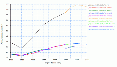
ImageThe power I get is a lot lower than what Vizard produces but that could have a lot of reasons.

After all this is a simulation and dyno’s are not exactly known to be the most consistent device on the planet ( of course Vizards is reading low.. ( Did anyone ever hear of any dyno that reads high by the admission of the owner..?? ”No mate my dyno reads high and is wildy inconsistent…that i’ll be $500 then  ”)

Unlike a BMW head, where you can just as well just run one cylinder at a time as they are all the same, the Siamese port head has heavy interaction as you have two horses feeding from the same bucket. Coupled to the end cylinders having their private exhaust ports that are a sensible length and the centre pair having to timeshare one port.

The interesting bit are the lower lines. Unlike a engine dynamometer it is easy to view the individual cylinders. For the most part this is pretty uninteresting as a sensibly designed engine makes the pretty much same power on all cylinders and has similar wave behaviour.

If we zoom in on the power of the individual cylinders you get quite an interesting view of things.

It is a simulation (never confuse the map with the terrain)  but I think that all basic ingredients are there for some additional insight into the weirdness of the a-series engine.

Centre-vs-End-Cylinders

The whole charge robbing concept that spurred creation of the scatter pattern cams  is mentioned on page 261 of the yellow book.

With a not too long cam the centre cylinders make more power up to about 5000 rpm , after that the end cylinders clearly have an advantage and the centre ones hit a wall from 5000 to 7000 rpm. Question is of course why!?

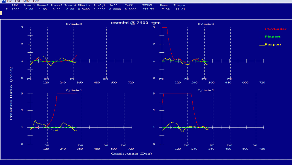
Is it the exhaust action ? You need a fair bit of energy/rpm to make a worthwhile suction pulse,  that would explain why the ends with the better  exhaust would fare better at higher rpm. It should show up in the wave traces.

Same for the intake ramming. Compared to an optimised BMW K head you have only a rudimentary intake ramming action to start with. Could the rather large difference be due to this ?

Well , this is something that has to be investigated further…

Tagged , , , , , , , , , , ,

Crouching siamese, hidden double headed dragon. Episode one

Part one: Exhausts

Do I look like I have a sense of humor ?… thought so.

The Siamese port head  might be ancient, but it sure makes things rather complicated rather quickly. The normal ”rules” , if there where any in the first place, do not seem to apply. This is odd as the rules mostly do apply, but you’re just looking at it wrong.  In this case there are two , or rather three things that set an A-series head apart from a 8 port head. Two Siamese intakes and one Siamese exhaust port.

The nice thing is, when you are trying to model something , is that you are forced to divide the process into small steps and looking at  it very closely.  If you look very closely at the above cat, the shape of the problem will become clearer as well.  Its head looks like a siamese port, the acute problem however it that the Siamese will become annoyed and poke your eye out.

Exhaust side

The double headed exhaust dragon.      Mostly harmless once you get to know them, unlike the Siamese cat.

First the exhaust side

The Cylinders 1 and 4 get the benefit of a private exhaust port that could be tuned somewhat conventionally. The centre pair of cylinders have to share space , although it is more like a time share apartment, as the pulses are 360 degrees apart and the exhaust valves of  cylinder 2&3 are not open at the same time.

In essence this makes it a 4-2-1 or Tri-Y system, where the plumbing is as follows : 1+4 and 2+3 into 1 collector.

The outer branches (1&4) can be varied to suit , but the hidden centre Y is fixed. Even though there is no sharing of port space as such, the effects of the branch/manifold ( a 3 pipe junction going to the inactive cylinder and the exhaust) on the wave behaviour has to be taken into account none the less.

So all Siamese 5 port exhausts are more or less 4-2-1 systems . Including the LCB (long centre branch), and even the 3-1 while  more like a 4-3-1,  you could also look at it being a 4-2-1 with super short secondary end branches

the fixed centre Tri-Y configuration

Due to the ports being what they are, the end branches are probably more easily tunable. In recent developments (uuhm in a engine where things are measured on a geologic time scale, meaning 6 years ago)   Maniflow came up with using a slightly enlarged stepped centre branch  that provided some gains when combined with a RCM ( reverse cone megaphone) in an effort to equalise things. Judging from what I have read so far , I suspect it being quite configuration specific. But it is certainly worth a closer look.

Simulation progress.

So far I have made progress on the simulation front, but it still is not on the level where I’m sufficiently satisfied with the correlation to measured data .  Where a simulated BMW K 16v head conversion spits out very decent curves on the first try , the Siamese head is a little , well quite a lot,  more involved and takes a lot longer ( a few hours @ 2.8 Ghz vs about 40 minutes for the 16v head) to calculate as well, due to the number of branches and port interaction involved.

1360 cc a series bottom end coupled to a 16v K1100LT head with tuned 280 mm intakes into a 1380 cc plenum and single 44mm throttle body. Exhaust is a 4-1 header into a single silencer (615mm primaries, 30mm diameter into 55mm merge collector 345mm long). These values are generated by Pipemax and seem to work quite well. Fuel is Unleaded +5% alcohol like we get in Mainland europe at prices that’ll make even the Redneckest V8 driver seriously consider buying a bicycle.

slightly different specs but at least it is an engine dyno. 1380 cc w. 16 v head w. RS cams. short ITB’s with rampipes. 4-2-1 header. into standard mini system.

the itb’s with open rampipes are a tad noisy and the combination of longer rampipes in a plenum both damp noise and boost midrange torque quite considerably at the expense of some top end power (lets face it, for a road going car anything over 6,5k is not all that useful and with 160 nm of torque in a 650 kg car it will go like stink anyway)

The beauty of this simulation is that you can actually look at the wave traces in ”real time” . Down side is that it is not always evident why a certain pattern produces more more torque than another. Furthermore my simulated engine is very prone to having a huge dip at 3000 rpm that I have not seen in real life, and does not produce power like it should. Well I’ll have to soldier on on that front.

I’m doing this all still on a test version of EngMod4T, but I will buy it as you really get an insight in the matter as presented in the Blair 4 st book.

Tagged , , , , , , , , ,

Testing the simulated water

As I still need some parts for a bore adapter to get sensible results for the 202 project, I am tryingmy hand at bit of simulation. In this case EngMod4T, one of the few that you can use to simulate the blasted siamese ports. I am using a trail version just to see if I can wrap my head around the various concepts.

Luckily I was battling myself  through Blairs 4 stroke book on which this is all based so most of it is reasonably straight forward. Some of it decidedly not, especially the heat and combustion modelling is rather complicated. Furthermore constructing a reasonable geometry is not straight forward

First step is to model a bog standard 1275 (well 1310). My efforts so far have been less than stellar.. it does not seem to want to run faster than 4000 rpm using a cam I know will rev to 7500 rpm easily .. well I must be doing something wrong then.

The program is very capable and can simulate even odd stuff like the amount of noise generated, bhp per cylinder, EGT’s etc etc.  But GIGO applies firmly.. and so far I obviously have been feeding it BS 🙂

Funny thing is that the most essential tool to have when using this program is a note pad and a pen to sketch the various pipes and collectors with the dimensions so you can keep track.Image

Tagged , , ,

small gains in high plains

I have found a tiny but worthwhile bit more flow ( about 1,9 cfm to slightly above 125 cfm@28 inch depression) and lost none just by reworking the chunky section between the two intakes with a narrow 30 cm piece of cloth backed  emery . the amount of metal removed is tiny but it now does not seem to stall as badly as before (i.e. you now actually get more flow when you lift more at very high lift whether as before, it just gave up). The gain is in a lift range that is very much in very hairy cam territory ( e.a. 11 to 12,5 mm with 1.5 rockers) or merely imaginary (14mm)> however it does emphasise that this area affects both very low and very high lift. It’s not really mentioned in Vizard’s’yellow book.

I guess i’ll beaver away at this region a bit more.

right hand side is being worked on

note the area as marked by the red arrows in the photograph above

Tagged , , , , , , ,

The Oz Option

Just as a weird idea..

The antipodean option

practical.?. not really

The australian manifold.. It is very impractical as you need to fit an Antipodean exhaust system as well.. but working from the idea that is good to initiate the turn as early as possible as the SSR is too small I just gave it a whirl.

The oz effect.. quite a bit of  mid lift loss and Lo and behold: quite a bit more of high lift gain..

remember those amber CRT’s of yore..

The idea of redirecting flow upward early on , to get a bit of high lift gain seems to work to some extent. It has to be seen it this can be achieved without the mid lift loss and a manifold that will fit  with a normal exhaust system

Tagged , , , , , , ,

Where to port next..

The problem with this port are many. For one, people just look at it and think.. that is a really bad push rod pinch for a 4v port..then find out it is not a 4v head. While the port is definitely odd it does seem to work.


Take for instance the BMW N52B25 inline 6 engine produced from 2004 to 2011 . It has all the modern trinkets, 4 valves per cylinder + VANOS and being a BMW is well engineered. Being an inline 6 it’s silky smooth too.

It produces 174 BHP/130KW from 2497cc or about 69 BHP/liter at 5800 rpm. and 92NM/liter torque from 3.5k to 5k.

Very similar figures are achievable from the little A-series with good mileage and good emissions . Had they bothered to rework the tooling so that the head was cast as it is ported (not exactly rocket science) it would have done so directly out of the box.

Well enough about why you have to just live with the fact that it looks odd but still works, and labour on to get it to work a bit better ; ) Even if standard rules do no apply.. if you look at the entire port as one piece.

I heard about flowballs.. do a google, it will reveal a hilarious video with a guy in a white coat.. As a professional white coat bearer I get acute multiple allegries, but that is mainly my personal problem. The basic premise is fine.. stick something in a port.. if it does not care.. there is no sense starting there. If it does not like it , you have found a part where air is flowing and that is a reasonable place to start removing metal.

Two thing I noticed.. the siamese section can be a bit larger I think. If i reduce the cross section only slightly (a 2mm layer of plasticine on the port floor) flow suffers quite badly. So the roof will be a bit reworked. And the upper corner after the pushrod pinch is very active. Downside is that it is very hard to reach.


the arrow indicicates the port where adding an obstruction, severely affect flow.
(done at 8mm lift)


Tagged , , , , , , , ,

Modified 12g940 Port Casting in silicone

A casting of the head I’m working on . Port of Cylinder 1&2, cast in one go with silicone with a bit more thixo added. So this time without a first thin layer with thixo and then a second. I must say the other mold of the 202 head is slightly better, even though it used slightly more silicone (because of the loss by making two batches), and was quicker to dry as well. The bowls are now cast solid and where a lot harder to extract this way. But the Siamese section is still hollow, so with a little wd40 and some pressing of my fingers it came out fairly easy.

I worked on the #2 port so if you see differences it is due to this fact.

12G940 bottom view port #1+2 cylinder.

As the curing took longer than last time/I expected. I managed to rip the right hand bowl a bit when i tried getting valves out too early.

note difference between left and right port ( left is the one I’m working on)

Side view. Note that due to the softness of the silicone the port sags a bit on the valves ,so the port floor is slightly more horizontal than it looks now

Tagged , , , , , , , ,